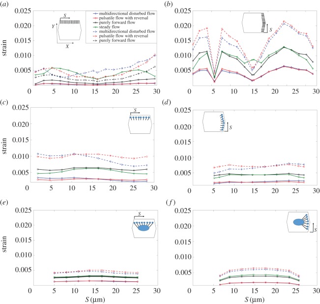
Figure 5.
The bending strain along the SFs in ECs exposed to shear stress. (a) SFsPP–APL–ADJs, (b) SFsPL–APL–ADJs, (c) SFsPP–APL–FAs, (d) SFsPL–APL–FAs, (e) SFsPP–FAs–NU, (f) SFsPL–FAs–NU. Note the same directions (X and Y) shown in the inset of a applies to all other parts. Note that t* is the relaxation time. (Online version in colour.)

