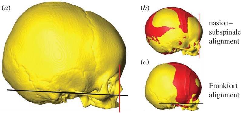
Figure 2.

Orientation of the in silico (B) and in vivo skulls. The red line passes through the nasion and the subspinale and defines the orientation of the skulls in this study. The Frankfort plane is shown in black and should be parallel to the ground for a normal head position. (b) and (c) show the in silico (B) model (seen in red) and the in vivo skull aligned with each other using the two orientations described.
