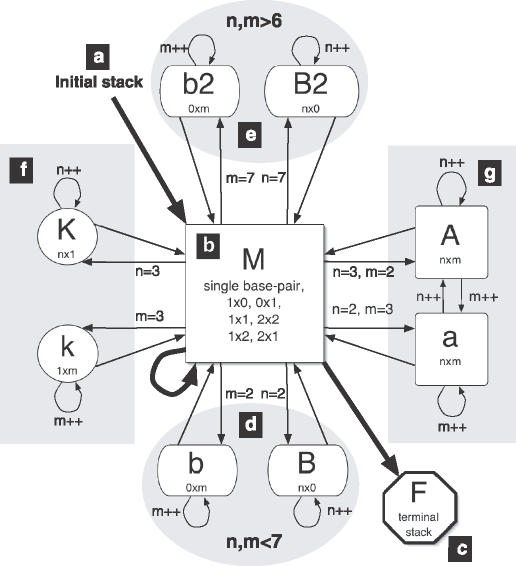
Figure 2.
This flowchart illustrates the bindigo algorithm, described in the text and in the recursion relations of online Supplementary Material, in terms of the matrices representing the different structures. An arrow into a matrix represents the free energy of the structure from the origin matrix feeding into the recursion relation of the destination. The numbers next to the arrow indicate the initial size of the loop considered by the matrix. Each alignment beginning with an initial stack (a) and concludes with a terminal stack (c), looping through base pairs (b) or bulge loops of various degrees of asymmetry (d–g) in between.

