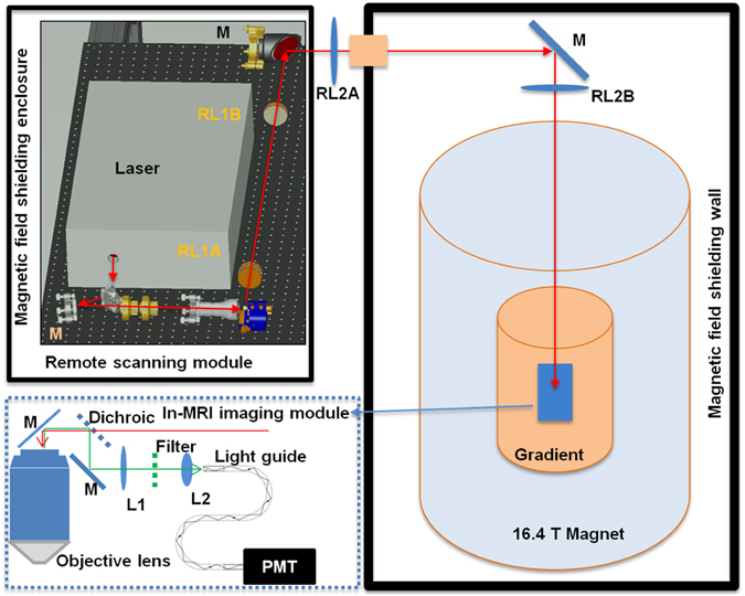
Figure 1.

Schematic of the MRI-compatible TPM imaging system. The laser scanning module (upper left corner) was located outside the 16.4T magnet room and contained inside a magnetic field shielding enclosure. The excitation laser beam was guided to the in-MRI imaging module inside the magnet by two sets of relay lenses (RL1A, RL1B, RL2A and RL2B) and mirrors (M). The in-MRI imaging module (enclosed by the blue dotted box) comprised an objective lens, a dichroic beam splitter, an optical mirror, a filter and two lenses (L1 and L2) which focused the two-photon excited fluorescence emission onto the entrance port of a 9 meter long fiber light guide. The exit port of the light guide was in contact with the front window of a GaAsP PMT housed inside the enclosure of the remote scanning module.
