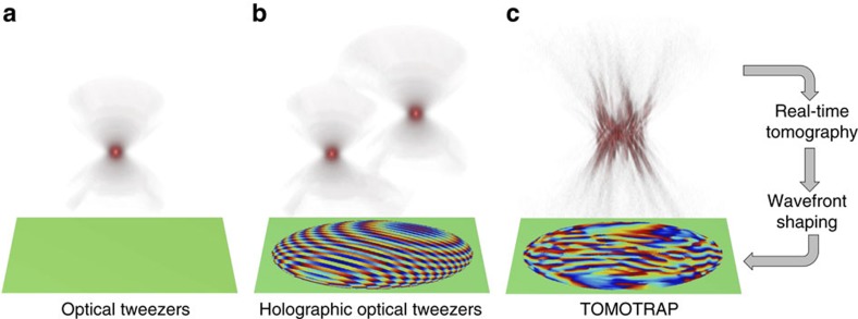
Figure 1. Schematic diagrams of various optical tweezers.
(a) Single-beam optical tweezers, (b) holographic optical tweezers and (c) TOMOTRAP employing real-time 3D refractive index tomography and wavefront shaping. The 3D beam intensity generated by each of the optical tweezers is depicted on the top, and the phase component of the complex optical field of the trapping beam is shown on the bottom.

