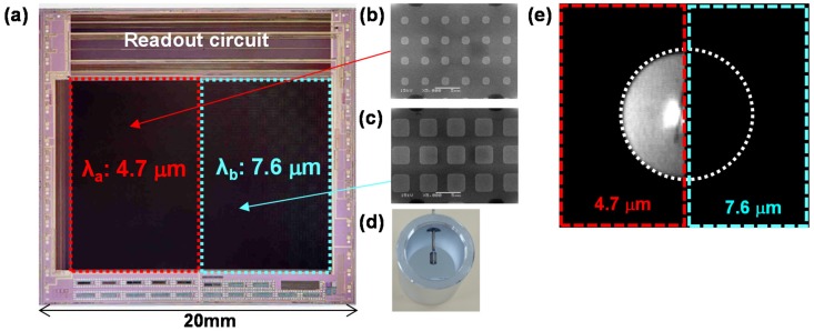
Figure 7.
(a) Optical microscopy image of the developed image sensor with two TH MIM-PMAs. SEM images of MIM-PMAs integrated in the (b) left and (c) right halves of the pixel array; (d) Optical image of the light emitter used in the image; (e) Image of the light emitter obtained using the developed image sensor with the narrow bandpass filter centered at 4.7 μm.

