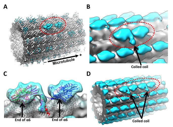
Figure 3. 3D reconstruction of kinesin dimer.
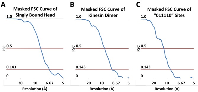
(A) The kinesin dimer density map (low-pass filtered to 8.5 Å) shows two heads (circled with red dashed line) that bind sequentially along one protofilament. (B) Same map low-pass filtered to 15 Å. Arrow points to the density corresponding to the coiled coil. No contact between the coiled coil density and the microtubule surface is evident in our map. (C) Crystal structures of kinesin motor domain (PDB ID: 1MKJ, 3KIN) are fit into the trailing head. Direction of the coiled coil density in the map is consistent with the PDB models. Additionally, 3J8X is fit into the leading head. Arrows point to the ends of helices α6, where the neck linkers originate. The coiled coil density appears closer to the trailing head, because the end of helix α6 is closer to the minus-end side of the motor domain. The neck linker from 1MKJ can extend from the coiled coil to the ends of helices α6 in both heads. (D) Parallel 3D reconstruction derived from ‘011110’ sites, showing two neighboring pairs of kinesin dimers. FSC curves are shown in Figure 3—figure supplement 1.


