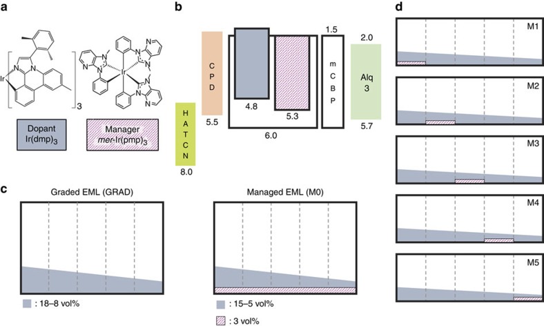
Figure 2. Energy and doping schemes of the PHOLEDs.
(a) Molecular formulae of Ir(dmp)3 and mer-Ir(pmp)3, used for the dopant and the manager, respectively. (b) Energy level diagram of the PHOLED with the manager, denoted ‘managed PHOLED'. Numbers in the figure are energies referred to the vacuum level. (c) Doping scheme of the 50 nm-thick EML for the graded-EML and managed PHOLEDs, denoted as GRAD and M0, respectively. GRAD has the dopant graded from 18 to 8 vol% in the mCBP host, while M0 is a similarly graded device but with the 3 vol% of the manager replacing the dopant of the same amount, compared to GRAD, to keep the total doping concentration the same for both devices. (d) Managed PHOLEDs M1–M5 have selectively doped 10 nm-thick zones of the EML. The zones have a manager doping of 3 vol% substituting the dopant of the same amount. The other details of the EML are identical to that of GRAD.

