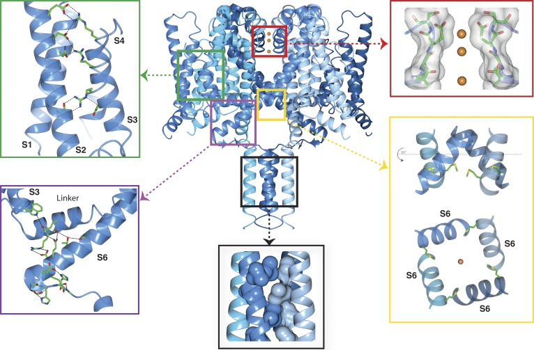
Figure 1.
Functional regions of the open activated full-length NavMs sodium channel. The four monomers of PDB ID 5HVX are depicted in ribbon motif in different shades of blue. The boxed regions point to expanded views of the VS, SF, pore gate, CTD, and IM. Top left (green box) inset: VS helices, showing the side chains of the canonical arginines of the S4 helix (indicated in the Fig. 4 sequence figure) and their partners in helices S1, S2, and S3. These are the ion pairings expected for an activated (“outwardly facing”) VS. The α-helical transmembrane helices are in cartoon ribbon depictions, whereas the top of the S4 helix, which is a 310 helix, is in worm depiction. The latter feature is consistent with the proposal that the transition from inactivated (fully α-helical) to activated states (310/α-helical) would involve changes in the helical parameters, as well as the arginine bonding partners (Villalba-Galea et al., 2008). Top right (red box) inset: The SF, with backbone and side chain atoms (only two subunits shown), is depicted as sticks overlaid in surface display mode; the three sodium ions are orange balls (radius not to scale, for ease of visualization). The closest residue to any of the ions is E178, which is adjacent to the top sodium ion, as previously seen in the NavMs pore structure (Naylor et al., 2016). All of the ion–polypeptide distances are too long to involve direct contacts and so must be via (mostly disordered) water molecules. Bottom right (yellow box) inset: (top) The open pore gate in S6 is depicted in ribbon mode with the side chains shown in stick mode for the Met222 residues, which correspond to the region previously identified as the closed channel gate constriction. The bottom panel is a 90° rotation view showing the end-on-view of the pore gate, again with the Met222 side chains shown. Bottom middle (black box) inset: The coiled-coil region of the CTD, with the hydrophobic side chains forming the knob-into-holes motif, shown in space-filling depiction (for clarity only the side chains from two of the helices are shown). Bottom left (purple box) inset: The IM showing the extensive network of hydrogen bonds and ion pairings (dashed black lines) involving both side chains and peptide backbone moieties. The S3, S4–S5 linker, and S6 helices are depicted in ribbon motif. The residues involved in the hydrogen-bonded network are shown as sticks in CPK coloring. This and the other graphics figures were created using CCP4Mg (McNicholas et al., 2011) software.

