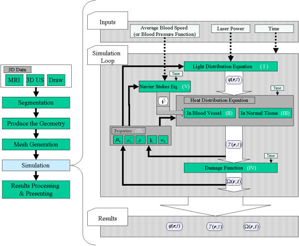
Figure 3.
The simulation loop. The figure shows the simulation flow chart as a step in the imagined surgical planning system (left side). The future goal of the surgical planning system is to verify the three parameters governing a laser treatment: the applicator position, the laser power, and the exposure duration. The temperature starting point of the volume is set to normal body temperature. Three input parameters are taken: average blood velocity, laser power, and application time (right side: input). The main part of the simulation is the loop, which calculates the variables in the forward steps, then updates the values of the different properties (parameters) in the backward step according to the results of the forward step. The loop follows the section materials and methods and uses its nomenclature for variables and functions (right side: loop). The output of the solver consists of three parts: the light energy fluence rate φ(r.t), the temperature distribution T(r, t), and the damage Ω(r, t) (right side results). The results are explicity shown in figures Fig. 4 and Fig. 5. The roman numbers (I-VI) refer to the equations in the text.

