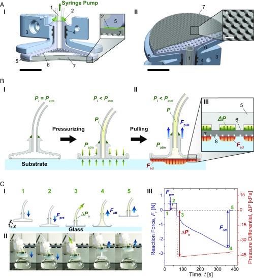
Fig. 2.
Schematics of structure, mechanism, and a representative adhesion test of the soft adhesion system. (A) A cross-section of 3D assembly of the proposed system from side (I) and from bottom (II) of the system. 1: silicone tubing, 2: vinylsiloxane, 3: outer case, 4: rubber ring, 5: soft chamber, 6: spacer between the chamber and the FAM, 7: FAM, and 8: mushroom-shaped PDMS microfibers. [Larger scale bars (black) indicate 5 mm, whereas the smaller scale (white) inside of the inset in II corresponds to 100 μm.] (B) A schematic of the proposed system when pressurized with a negative pressure differential (ΔP) (I) and pulled with a pull-up load (Fpull) (II). The inset (III) shows a schematic of pressure distribution between the spacers in the soft chamber and adhesion stress on the contact interface. (C) Adhesion test of the soft system. A schematic of experimental procedure (I), snapshots of the soft system under a negative pressure differential on a 30-mm-diameter glass hemisphere in accordance with each step (II), and corresponding profiles of reaction force (Fr) and pressure differential inside the chamber with respect to elapsed time (III). The initial pressure (ΔPo) here is approximately −47 kPa. The numbers indicated in green are correlated with the experimental procedure 1: approaching, 2: preloading, 3: applying initial pressure, 4: pulled off, and 5: detached.

