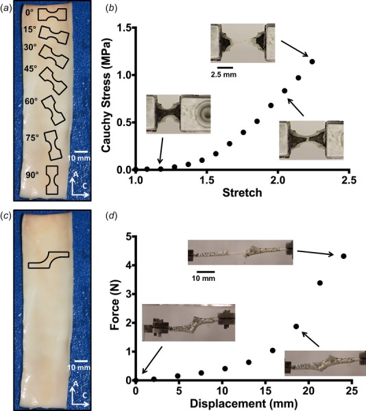
Fig. 1.

(a) Outlines of dogbone sample geometries are shown along the axial length of the vessel (not drawn to scale). Angles were taken to be relative to the circumferential orientation (0 deg). Scale bar shown in white. (b) A representative stress–stretch curve for one uniaxial sample, with corresponding tissue images during testing. (c) Outline of the shear lap sample geometry (not drawn to scale). (d) A representative force–displacement curve for one shear lap sample. Failure initiated near the overlap region of the sample and propagated across the overlap region (lap across failure).
