
Figure 1.
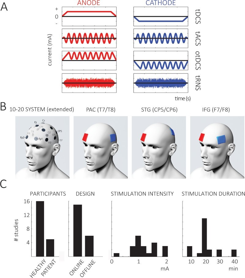
(A) Current waveforms used for stimulation during the different types of tES. In addition to the relatively established tDCS and tACS methods (first and second row, respectively), these methods can be combined (oscillatory tDCS, otDCS, third row), or a noise with a broad spectral range can be applied (tRNS, fourth row). At the start (and end) of stimulation, current is commonly faded in (and out) to minimise sensations associated with stimulation. Note the opposite sign of the current for anode (left) and cathode (right). Redrawn, with modifications, from Herrmann et al. (2013) and Saiote et al. (2013). (B) Electrodes are commonly placed above the to-be-stimulated region. This panel shows these placements (according to the extended 10–20 system, chosen electrodes are shown in the leftmost panel) for the three groups of studies described in this review (T7/T8, above PAC; Cp5/Cp6, above STG/STS; F7/F8, above IFG; for IFG, other electrode positions have been described). Blue (cathodal) electrodes are shown exemplarily above target regions of the left hemisphere, and the positions of the red (anodal) “return” electrodes are shown as attached to the transorbital region of the contralateral hemisphere (although this approach is commonly found in the literature, it is a rather arbitrary decision, see text for discussion of associated problems). In practice, the position of the “return” electrode (e.g. the anode for cathodal stimulation), the hemisphere (left, right, or both) for the “stimulation” electrode (e.g. the cathode for cathodal stimulation), and the direction of current flow (cathodal, anodal, or oscillatory) varies across studies. (C) Number of different studies (out of the 21 studies reviewed in detail in the section “Key empirical contributions”) which employ different participants, experimental designs (left two graphs), and stimulation parameters (right two graphs). The diversity of these parameters across studies makes comparisons difficult.