
Fig. 4. Delayed transit of activated cells in the MMM.
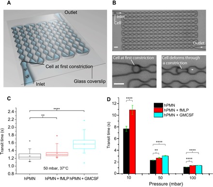
(A) Schematic of the MMM, illustrating constrictions and inlet and outlet channels from and to reservoirs (not shown). (B) Actual micrograph of MMM showing all 187 constrictions. The minimum gaps at the constrictions are smaller than the diameter of cells, ensuring that each cell is repeatedly deformed during the advection. (C) Box plots of average transit times at 50-mbar driving pressure for various cell states (n = 50 per state), showing a statistically significant increase in transit times for all activated cells, compared to resting neutrophils. (D) Bar graph of average (error bar is SEM) transit times of resting, fMLP-, and GM-CSF–treated neutrophils at 37°C and pressures of 10, 50, and 100 mbar. Note that, at 10 mbar, the GM-CSF–treated cells could hardly make it through the device; hence, there are no data for this cell state at 10 mbar. **P < 0.01 and ****P < 0.0001 (significant difference). Scale bars, 15 μm.