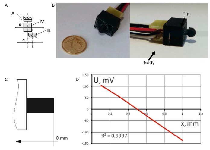
Figure 6.
(A) Configuration of the differential transducer with Hall-effect sensors—one magnet system applied in the technology demonstrator: M—micromagnet, A and B—sensors, x—linear displacement, x0—phase shift at maximum sensitivity of Hall sensors; (B) Visualization and (C) design of the sensor; (D) Physical experiments—experimental characteristics of the sensor. Reproduced from [19], with permission from Springer International Publishing AG, Cham, Switzerland © 2016.

