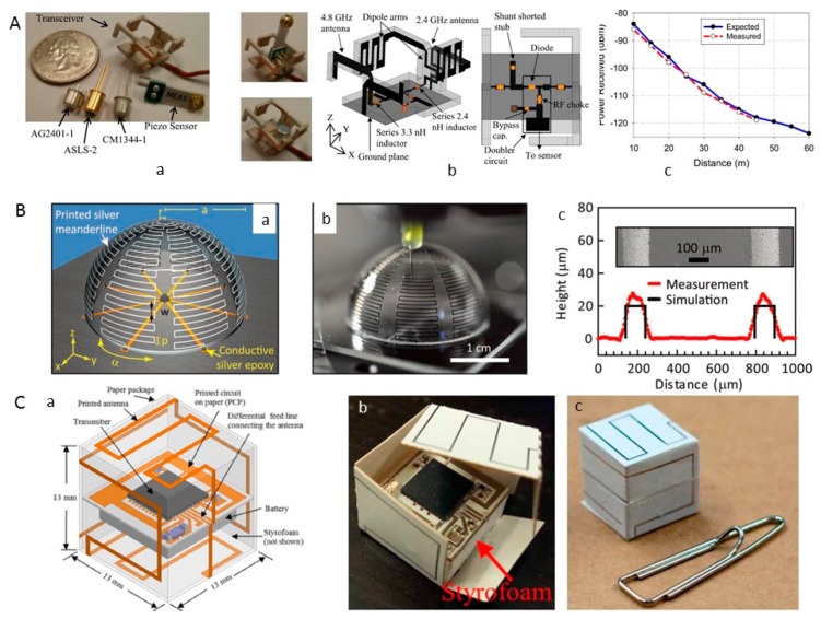
Figure 12.
(A) Photograph of the fabricated transceiver and the sensors (a), a CAD illustration of the transceiver design (b), the measured and expected received return signal strength versus distance using a 43 dBm EIRP transmitter and 11 dBi gain receiver (c). Reproduced from [41], with permission from IEEE © 2015; (B) Schematic illustration of an electrically small antenna with labeled geometric parameters (a) and the optical image of an antenna during the printing process (b), optical profilometry scan of representative meanderlines on electrically small antennas with the background surface subtracted and scanning electron microscopy image of these features (inset). Reproduced from [39], with permission from WILEY-VCH Verlag GmbH & Co. KGaA, Weinheim, Germany, © 2011; (C) Sensor model (a) and completed sensor (b,c). Reproduced from [43], with permission from IEEE © 2014.

