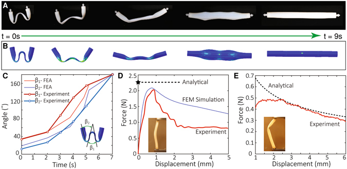
Figure 2.

Properties of the slitted tubular struts via 3D printing. (A) The snapshot images of the free recovery sequence of a strut at 65 °C. (B) The predictions from the corresponding finite element method (FEM) simulation. (C) The opening angles of the strut during the free recovery and the comparison with the FEM simulation. The inset shows the definitions of the two opening angles. (D) The critical load of a single strut during uniaxial compression from the experiment and the FEM simulation. The inset shows the experimental setup. Considering the boundary condition in the experimental setup, a 0.75 effective length ratio gives the upper bound on the critical buckling load of a single strut. In practical designs, because the joints in our tensegrity are almost free in rotation, 1.0 effective length shall be used. (E) The critical load of a single strut during its recovery. Derivation for the analytical prediction is elaborated in SI. In the experiment, a small initial displacement (1 mm) is imposed to prevent the opened cross section from closing.
