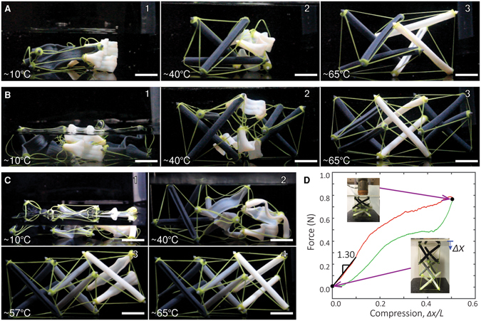
Figure 4.

Programmed deployment of layered tensegrity structures. (A) Programmed deployment sequence of the 2-layer tensegrity using 2 different SMPs for the struts [DM-1 (the dark grey material) and BM (the white material)]. (B) Programmed deployment sequence of the 3-layer tensegrity using 2 different SMPs for the struts [DM-1 (the dark grey material) and BM (the white material)]. The two end layers have struts made with SMP of a lower T g than the middle layer. (C) Programmed deployment sequence of the 3-layer tensegrity using 3 different SMPs for the struts. The three SMPs have increasing T g’s from left to right. The darker the color, the lower the T g. (D) Compression test of the deployed 3-layer tensegrity made with 3 different SMPs. The test reveals a maximum compression in the struts around 0.12 N. The scale bars represent 15 mm.
