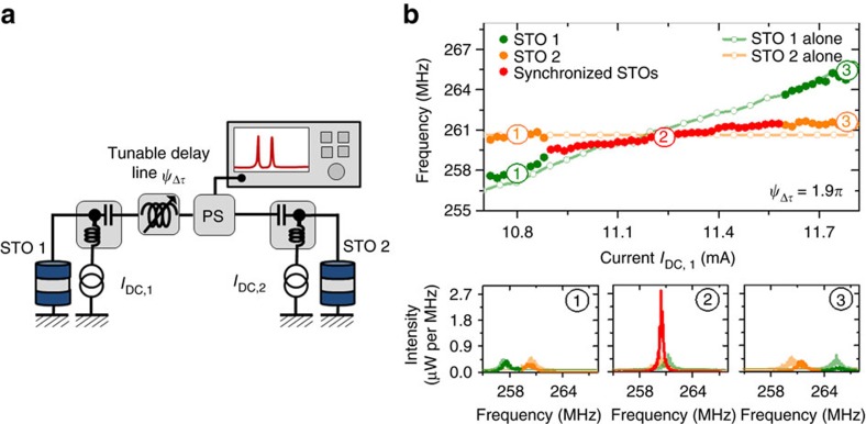
Figure 1. Mutual synchronization of two spin torque oscillators.
(a) Scheme of the electrical circuit for the mutual synchronization of two oscillators independently supplied by two currents and connected through the microwave port of two bias tees with a tunable delay line ψΔτ. The detected signal is measured using a spectrum analyzer, connected to the delay with a −6 dBm power splitter (PS). (b) Evolution of the frequency of the interacting STOs as a function of IDC,1 while IDC,2 is fixed to +10.6 mA. Corresponding spectra for IDC,1=+10.8 mA (1), +11.25 mA (2), +11.8 mA (3) (Non-interacting oscillator properties when one is switched off are in orange and green softened curves).

