Figure 3.

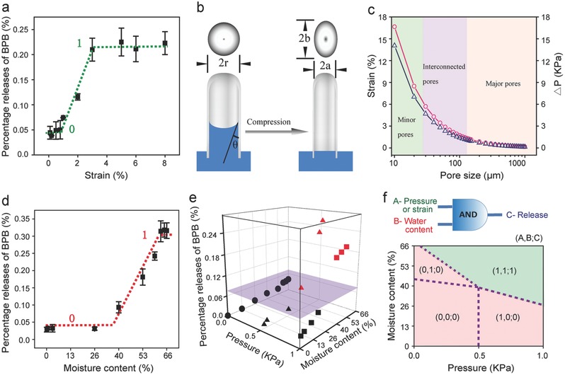
Mechano‐active CCS for AND logic release. a) Cumulative release of BPB from CCS at different strains. CCS has a moisture content of 66% and is subjected to ten compression cycles at each strain. b) Simplified cylindrical pore model for the analysis of water expelled from pores in CCS. Before compression, the pore has a circular cross section with a diameter of 2r and the hydrophilic liquid has a contact angle of θ. After compression, the deformed cylindrical pore has an elliptical cross section with two axes of (a) and (b). c) Estimated counter pressure (∆P, blue triangles) and compressive strains (εrepel, red circles) as a function of pore size. d) Cumulative release of BPB from CCS at different moisture contents. CCS is subjected to ten compression cycles at a pressure of 0.5 kPa. e) 3D diagram of AND logic release in CCS, where the vertical axis is the cumulative release of BPB and the horizontal axes are moisture content and pressure, respectively. CCS is subjected to ten compression cycles at each point. f) Logic map showing True (1) and False (0) relations between dual inputs of A) pressure/strain and B) moisture content, and C) output of release. Red zone represents C = 0 (False) and green zone represents C = 1 (True). Dot lines represent the thresholds of logic gates A and B.
