
Fig. 2.
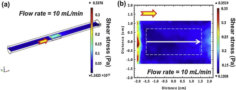
A typical single CFD contour (a) and a 2-D slice of test area in a white dashed box (b) at the inlet flow rate of 10 ml min−1 condition. The arrows on the channel indicate the flow direction of corrosion medium in the bioreactor.
Official websites use .gov
A
.gov website belongs to an official
government organization in the United States.
Secure .gov websites use HTTPS
A lock (
) or https:// means you've safely
connected to the .gov website. Share sensitive
information only on official, secure websites.
A typical single CFD contour (a) and a 2-D slice of test area in a white dashed box (b) at the inlet flow rate of 10 ml min−1 condition. The arrows on the channel indicate the flow direction of corrosion medium in the bioreactor.