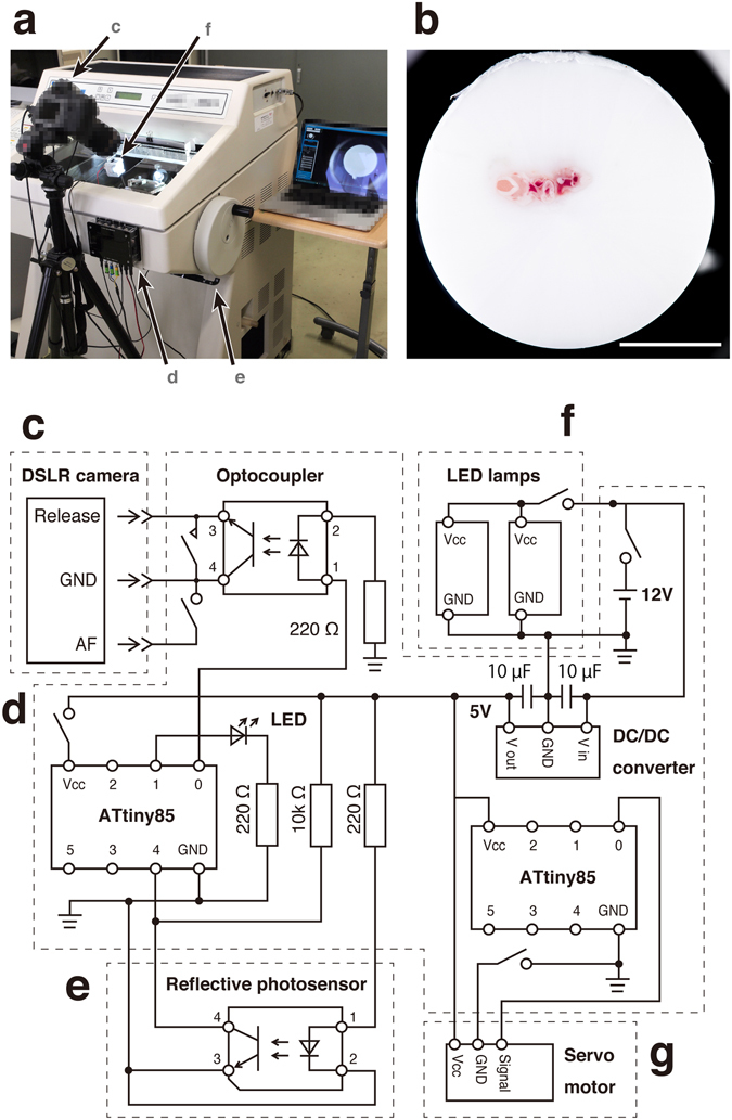
Figure 1.

The CoMBI system. (a) Photograph of the system. The camera (c) is placed in front of the cryostat. The controller (d) is attached to the front panel of the cryostat. The sensor (e) is attached close to the cryostat handle to detect the handle position. The illumination (f) is set in the chamber. (b) An example of the block-face image shows the clear outer circumference. (c–g) Circuit of the system: camera (c), controller (d), sensor (e), illumination (f), cleaning brush (g). An ATtiny85 microcontroller (left) receives signals about the position of the cryostat handle from the sensor (e), and triggers release of the camera shutter (c) using an optocoupler. The illumination (f) consists of two LED lamps on the door to illuminate the block-face orthogonally. The cleaning brush (g) consists of a servomotor and three brushes attached to the back of the knife holder to clean the block-face during imaging. Bar in b: 5 mm.
