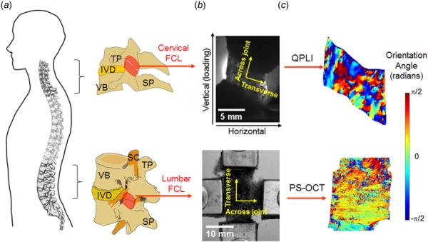
Fig. 1.

Anatomy and imaging of FCLs in the cervical and lumbar spinal regions. (a) Schematics showing the lateral view of the spine and vertebrae to demonstrate the overall anatomy of the cervical and lumbar facet joints and the location of the FCL in each spinal region. (b) The relevant anatomical and loading directions are labeled on the grayscale images of isolated cervical and lumbar FCLs positioned on the mechanical testing devices. (c) Orientation angles showing collagen alignment measurements using the quantitative polarized light imaging (QPLI) and polarization-sensitive optical coherence tomography (PS-OCT) for cervical and lumbar FCLs, respectively. TP: transverse process; SP: spinous process; IVD: intervertebral disk; VB: vertebral body; and SC: spinal cord.
