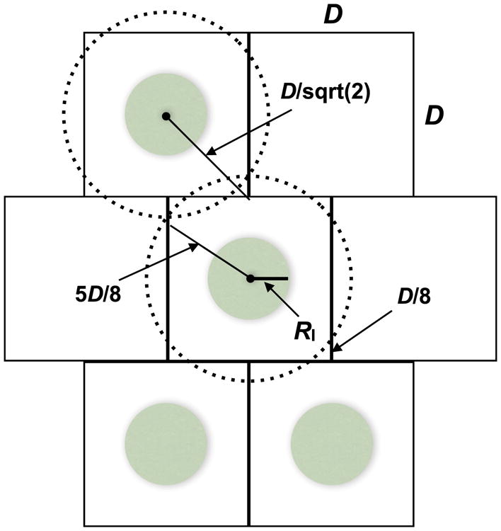
Fig. 6.

Optimal spacing. The green circles within the D × D squares represent release areas with radii RI. If the release areas were laid out on a regular grid, each expanding wave would have to travel to the corner of the enclosing square, a distance of (D/√2) – RI, to transform the entire target area. In contrast, by offsetting the release centers between adjacent rows, as illustrated, each wave must travel only (5D/8) – RI for area-wide transformation.
