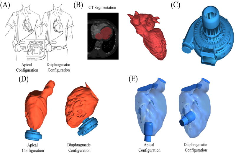
Figure 2. Generation of Cardiac Anatomy.
Virtual surgery was applied to implant the VAD in two surgical configurations: apical vs. diaphragmatic configurations. (A) Illustration (reprinted with permission from Gregoric et. al. 2011), shows both the apical (left) and diaphragmatic (right) configurations in situ. (B) The blood flow path in the left heart was segmented from contrast-enhanced CT scans of a heart failure patient prior to VAD implantation. (C) 3D geometry from the Heartware HVAD. (D) The VAD geometry was combined with the heart geometry to represent both surgical configurations. (E) The HVAD cannula geometry was subtracted from the fluid domain and its distal end defined as the outlet, thus defining the final geometries used in simulations.

