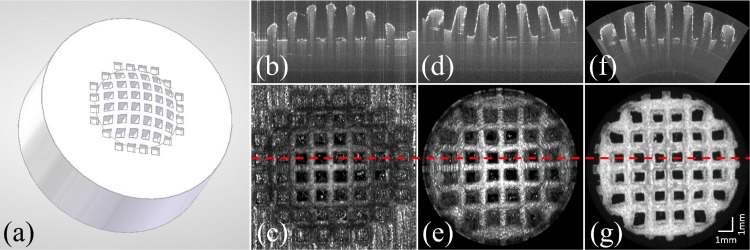
Fig. 4.
(a) 3D model of the test object. (b) B-scan of the test target and (c) en-face projection imaged with the standard scanning optics as shown in Fig. 2(b). (d) B-scan of the same feature as in (b) and the en-face projection (e) of the test target imaged with the conical setup shown in Fig. 2(a). (f) and (g) show the corresponding B-scan and the en-face map of the surface of the test target after correcting for the distortions introduced by the scan pattern (but not for field distortions introduced by the lens, which are responsible for the remaining distortions at the periphery). The red dashed line represents the position of the corresponding B-scans.

