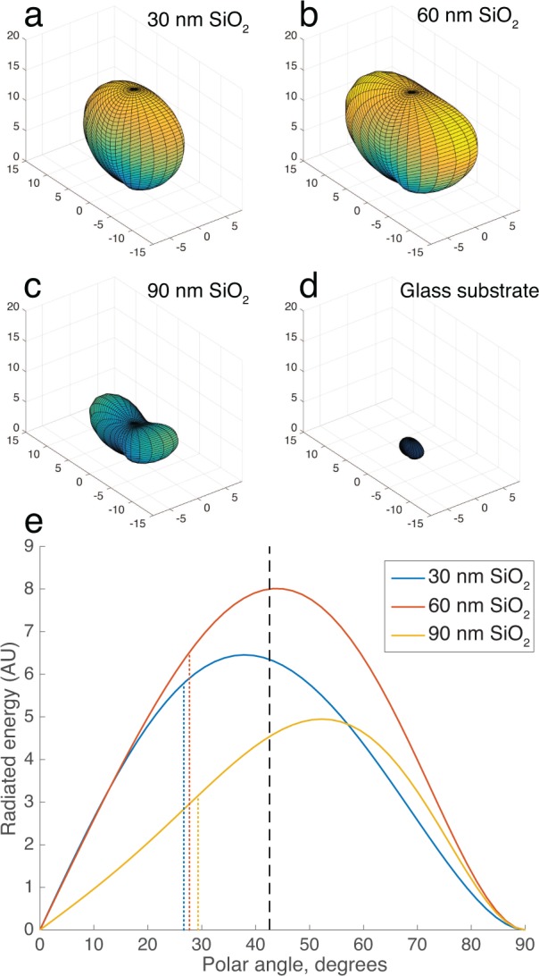
Fig. 3.

(a–c) 3D simulated plots of the radiation pattern (Poynting vector magnitude) of total back-scattered light Escat of a 100 nm virus particle (n=1.5) on SP-IRIS substrates with a range of film thicknesses, compared with (d) a glass substrate (arbitrary units). Illumination is a normal-incident linearly polarized plane wave with λ = 530 nm. (e) Distribution function of back-scattered radiation vs polar angle (i.e, from surface normal) for the cases shown in (a–c). The dashed line indicates the maximum collection angle of a 0.9 NA water-immersion objective. Dotted lines indicate the mean polar angle of the collected light, for each case.
