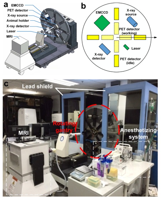
Fig. 1.

System overview of our pentamodal imaging system. (a) CT, optical and PET imaging instruments were arranged on a rotating gantry. (b)The polar coordinate system indicates the arrangement of instruments in the schematic diagram of our imaging system. Different colors are assigned for different sub-systems: yellow for PET sub-system, green for optical tomographies, and blue for CT sub-system. (c) Photograph of the overview of the system is taken before the assembling of the light shield chamber. An MRI system for verification is placed on the opposite of the rotating gantry.
