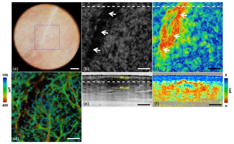
Fig. 5.
Scar images by dermoscopy guided MF-OCT. (a) Dermoscopy image. (b, e) Intensity OCT and (c, f) PS-OCT images in the x-y and x-z plane respectively (see Visualization 2 (2.4MB, MOV) ). (d) MIP angiographic OCT image with depth resolved color mapping in the x-y plane. A blue dashed lined box indicates FOV of MF-OCT. White dashed lines indicate locations of the cross-sections and depth-sections. White arrows indicate the highly scattering and birefringent regions in (b, c). Yellow dashed lines indicate the depth range of angiographic OCT image. Scale bars are (a) 1 mm and (b-f) 500 μm.

