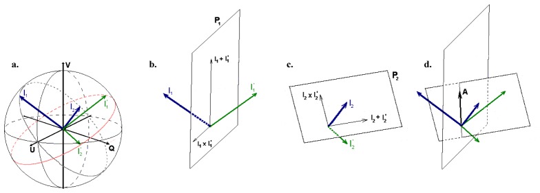
Fig. 4.
Birefringence calculation illustrating (a): the surface states, I1 and I2, in blue and the reflected states, I’1 and I’2, in green, (b, c) the planes P1 and P2 that span all possible rotation axes, and (d): the intersection of the planes resulting in determination of the optic axis. Reprinted from Ref [13].

