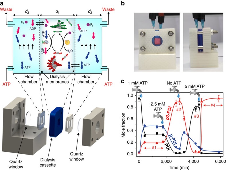
Figure 4. Continuous flow device and supramolecular non-equilibrium steady states.
(a) Principle of operation and CAD design of the continuous flow device based on a clamped dialysis cassette. The average gap between the membranes d1 is 1.9 mm, the width of the flow chambers d2 5.1 mm. (b) Front and side view of the three-dimensionally (3D) printed device, also showing the inlet and outlet needles inserted through the silicon spacers. (c) Different NESS (plateau regions, no. 1−4), characterized by different molar fractions of the three species PDI, p-PDI and p2-PDI (by LC–MS analysis), can be obtained using the continuous flow device, depending on the influx of the fuel ATP. Solid lines are drawn to guide the eye. The taps are placed in correspondence of the time(s) at which we changed the ATP concentration of the solution that is continuously flowed through the lateral flow chambers. Namely, at t=50 min we started to flow ATP 1 mM, at t=1,770 min we switched to ATP 2.5 mM, at t=3,170 min we started to flow buffer without ATP and at t=4,440 min we switched to ATP 5 mM. For all NESS experiments: 0.085 μM PKA and 0.097 μM λPP. The error bars were set to 6% of the corresponding value. The latter is the maximum error observed in the determination of the molar fraction when injecting 3 times in LC–MS solutions of known composition.

