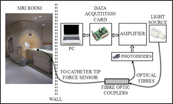
Fig. 1.

One representative experimental setup for evaluation of an intensity based fiber optic sensor for cardiac catheterization procedure on a healthy swine model (Polygerinos et al. [16]). The optoelectronic equipment was placed outside the MRI room. Fiber optic cables passed through the MRI patch panel for communication between sensor and signal conditioning instrumentations ©2011 IEEE. Signal conditioning circuitry can also be placed inside the MRI room with appropriate shielding as in Su et al. [17].
