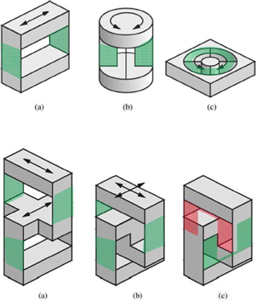
Fig. 2.

Top row: typical geometries of flexure design for 1-DOF fiber optic force sensors (a) and 1-DOF fiber optic torque sensors (b–c). Bottom row: typical geometries of flexure design for 2-DOF XY fiber optic force sensor. (a) Two serially connected linear stages. (b) Shifting down the upper stage for compactness. (c) Two U-shaped linear stages. The green shades indicate the flexure joint structure. [8] ©2008 IEEE.
