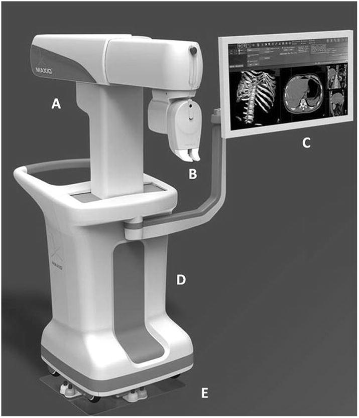
Figure 1. Robotic Positioning System.

Overview of the Robotic Positioning System used for performing the experiments.
A: Articulated arm capable of motion along three separate axes.
B: End effector of the robotic arm with the needle guide. Capable of motion around two axes for orienting the needle towards the target.
C: Monitor showing view of the onboard software used for planning needle placement and operating the robot.
D: Cart enclosing computer, control equipment and the robotic arm.
E: Docking plate used to accurately position the cart adjacent to the CT table and register the robot with the CT imaging workspace.
