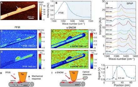
Fig. 5. PFIR microscopy studies on BNNT.

A) The topography of a BNNT on a gold substrate. (B) The FTIR spectrum of bulk BNNTs shows the phonon resonances but not the SPhP resonances that would be present above 1380 cm−1 marked in the gray box. (C) The PFIR image at the infrared frequency of 1390 cm−1. (D) The PFIR image at the infrared frequency of 1430 cm−1. (E and F) The s-SNOM images taken at 1390 cm−1 (E) and 1430 cm−1 (F) of the same region of BNNT are shown as references. A similar spatial distribution of the infrared response is observed. (G) PFIR spectra taken from a series of locations along the BNNT at 100-nm increments from the tube terminal show position-dependent variations with clear SPhP resonances. The spectra are vertically offset for clarity and were taken along the black dashed line in (A) starting 50 nm away from the terminal. (H) A possible SPhP excitation scheme for PFIR. (I) The SPhP excitation and detection scheme in s-SNOM. (J) Estimation of spatial resolution in the PFIR measurements from a cut profile of the BNNT [white line in (C)] is found to be 9.5 nm from the width between 90 and 10% of the height of the PFIR signal.
