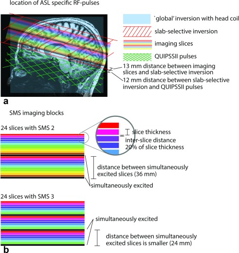
Figure 1.

(A) The SMS ASL acquisition setup overlaid on an anatomical image. The stack of slices with varying colors show the position of the imaging slices. The slices with the same color are acquired simultaneously. Slices with different colors are imaged in an ascending order. The light blue rectangle indicates the extent of a global inversion pulse when a head RF coil is used. The red stripe pattern depicts the dimensions of the slab‐selective inversion. It was made 13 mm broader (in the superior and inferior direction) than the dimensions of the block of imaging slices. The difference between the global and slab‐selective inversion results in the tagged bolus. The green hatch pattern shows the position of the QUIPSSII saturation pulses. (B) A detailed view of the SMS imaging blocks for SMS factors 2 and 3. With increasing SMS factor, the distance between simultaneously excited slices (indicated by the same color) decreases. ASL, arterial spin labeling; RF, radiofrequency; QUIPSSII, quantitative imaging of perfusion using a single subtraction II; SMS, simultaneous multi‐slice.
