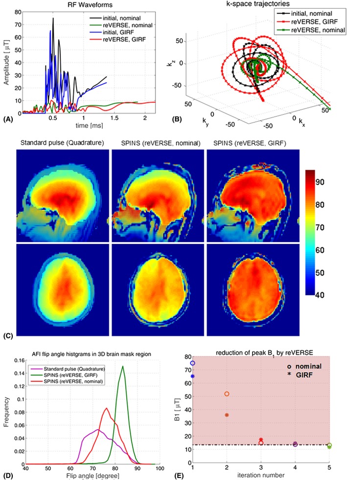
Figure 8.

A, Initial and reVERSEd SPINS pulses. B, Nominal and GIRF predicted k‐space trajectories. C, In vivo AFI flip‐angle maps using SPINS pulses designed with and without the GIRF correction (at the fifth iteration) and the hard‐pulse excitation at the quadrature mode of the transmit array. D, Histograms of the measured flip angles within the brain. E, Reduction in peak RF amplitude
