Abstract
Twisted two‐dimensional aromatic frameworks have been prepared by overcrowding the nodes with bulky and rigid substituents. The highly distorted aromatic framework with alternating out‐of‐plane substituents results in diminished interlayer interactions that favor the exfoliation and dispersion of individual layers in organic media.
Keywords: carbon nanostructures, materials science, nanocarbons, organic frameworks, twisted aromatic systems
The discovery of graphene1 has opened up exciting possibilities for developing two‐dimensional (2D) polymers,2 such as 2D conjugated microporous polymers (2D‐CMPs) and 2D covalent organic frameworks (2D‐COFs), for a wide range of applications,2 including electronics, energy conversion and storage, gas storage and separation, catalysis, and sensing. Synthetic 2D organic frameworks composed of fused aromatic rings3 have emerged as a highly tunable alternative to nanopore‐grafted (or holey) graphene, since they combine an extended 2D π system with permanent nanometer‐sized pores. Furthermore, since such 2D polymers are synthesized by bottom‐up approaches, heteroatoms can be incorporated into the framework with relative ease, which provides an additional way to modulate their electronic structure and their properties. For example, the exchange of C atoms for N atoms in 2D organic frameworks has resulted in more efficient materials for energy applications, such as electrocatalysts for the oxygen reduction reaction (ORR),4 the hydrogen evolution reaction (HER),5 supercapacitors,6 and batteries.6a, 7
The preparation of stable dispersions of individual layers of 2D organic frameworks would be ideal from several perspectives. First, it would facilitate the sorting of layers by size, composite preparation by solution mixing, chemical modification, and structural and optoelectronic characterization.8 Second, it would enable the formulation of such 2D materials in inks8 and thus would enable low‐cost, large‐area liquid‐deposition methods, such as spin coating, spray coating, or inkjet printing. However, similarly to graphene, synthetic 2D organic frameworks are very difficult to process because of the great tendency of the individual layers to aggregate by noncovalent interlayer interactions. Although several examples of the delamination of 2D organic frameworks by mechanical9 and solvent‐assisted methods,10 electrostatic repulsion,11 and chemical methods12 have been reported, these methods provide materials that are a few layers thick and thereby show that the individualization of layers is still a challenging task.
Herein, we report a new and unconventional approach for obtaining dispersions of individual layers of 2D‐CMPs composed of fused aromatic rings on the basis of the introduction of twists in their framework by overcrowding the nodes of the framework with bulky and rigid substituents, which are forced above and below the plane (Figure 1). The highly distorted aromatic framework with alternating out‐of‐plane substituents results in diminished interlayer interactions, thus favoring the exfoliation and dispersion of individual layers in organic media and leading to stable dispersions that can be processed into thin films. Direct drop casting of a dispersion of the twisted 2D‐CMP on glass and on glassy‐carbon electrodes showed the semiconducting nature and the ORR activity of this new member of the 2D materials family.
Figure 1.

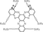
a) Chemical structure (with twist angles) of TIPS‐CMP and PM6‐DH2 calculated structure of a closed pore of TIPS‐CMP (top and side views). b) Chemical structure (with twist angle) and crystal structure13 of twisted‐HATNA (top and side views). Hydrogen atoms have been omitted from all structures for clarity.
Our twisting approach for the preparation of a 2D‐CMP is based on the introduction of rigid acetylene moieties with triisopropylsilyl (TIPS) groups at the nodes of the framework (Figure 1). In analogy to twisted 1,4,7,10,13,16‐hexa(triisopropylsilyl)ethynyl‐5,6,11,12,17,18‐hexaazatrinaphthylene (twisted‐HATNA),13, 14 the close proximity of the TIPS groups will force the aromatic framework to deviate from planarity, as there is not sufficient space to accommodate all the substituents in the same plane. We envisioned the preparation of a twisted 2D‐CMP by using the conditions described for the synthesis of pyrazine‐fused conjugated microporous polymers (Aza‐CMPs)3a by Jiang and co‐workers (Scheme 1). However, the Aza‐CMPs were synthesized by ionothermal methods, which require harsh conditions incompatible with TIPS substituents. For this reason, we first established a solvothermal method to prepare Aza‐CMPs under milder conditions, namely, the cyclocondensation of 1,2,4,5‐benzenetetraamine and 1,2,3,4,5,6‐hexaketocyclohexane in a 1:4 mixture of dioxane and acetic acid at reflux. These solvothermal conditions provided Aza‐CMP with nearly identical structural data (see Figures S1, S2, S3, S4, and S7 in the Supporting Information) to those of Aza‐CMPs obtained by ionothermal methods at low temperatures.3a The cyclocondensation of 1,2,3,4,5,6‐hexaketocyclohexane with 3,6‐di(triisopropylsilyl)ethynyl‐1,2,4,5‐benzenetetraamine15 in a 1:4 mixture of dioxane and acetic acid at reflux yielded TIPS‐CMP after purification (Scheme 1).
Scheme 1.
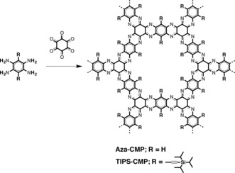
Solvothermal synthesis and structures of Aza‐CMP and TIPS‐CMP.
The structure of TIPS‐CMP was confirmed by a combination of different characterization techniques (see the Supporting Information for details). In the FTIR spectrum of TIPS‐CMP, the vibration bands corresponding to the monomers had disappeared, and new bands in agreement with those of Aza‐CMP, which was used as a planar reference, were observed (Figure 2 a; see also Figure S1). The FTIR spectrum of TIPS‐CMP (Figure 2 a) showed the disappearance of both the C=O (1663 cm−1) and NH2 (3444 and 3363 cm−1) groups of the precursors. The formation of new C−N bonds was evidenced by the appearance of an intense band at 1202 cm−1 as a result of the C−C and C−N stretching of the pyrazine rings, and the shift in the typical features of the aromatic rings from the starting material (1540 and 1460 cm−1) to TIPS‐CMP (1515 and 1454 cm−1). C(sp3)−H stretching vibrations were present in the spectra of both the starting tetraamine and TIPS‐CMP, and although a small feature at 2131 cm−1 could be observed for TIPS‐CMP, the band corresponding to the C=N/C=C stretching mode had almost disappeared, as expected for highly symmetric structures. These changes in the spectra were also reproduced in the case of Aza‐CMP, for which the bands at 2892 (N−H) and 1663 cm−1 (C=O) were not present in the final polymer, and an intense band at 1216 cm−1 indicative of the formation of the pyrazine rings was observed. Solid‐state cross‐polarization/magic‐angle spinning (CP/MAS) NMR spectroscopy of TIPS‐CMP was consistent with the proposed structure. The 1H NMR spectrum of TIPS‐CMP showed a signal centered at 0.12 ppm corresponding to the hydrogen atoms of the TIPS groups (Figure 2 b). As expected, the 13C NMR spectrum of TIPS‐CMP showed a broad signal (typical of quaternary carbon atoms) corresponding to the sp2‐ and sp‐hybridized carbon atoms and two distinct peaks in the aliphatic region at 18.6 and 11.9 ppm corresponding to the two types of carbon atoms of the TIPS groups (Figure 2 c). The 29Si NMR spectrum of TIPS‐CMP showed one signal at −6.45 ppm, which corresponds to the silicon atom of the TIPS groups (Figure 2 d).
Figure 2.
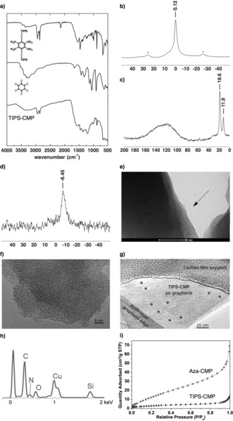
a) FTIR spectrum of TIPS‐CMP; b) solid‐state CP/MAS 1H NMR spectrum of TIPS‐CMP (* denotes side peaks); c) solid‐state CP/MAS 13C NMR spectrum of TIPS‐CMP; d) 29Si NMR spectrum of TIPS‐CMP; e) TEM image of TIPS‐CMP; f) HRTEM image of TIPS‐CMP; g) HRTEM image of an individual layer of TIPS‐CMP on graphene; h) EDX spectrum of TIPS‐CMP (Cu peak is due to the sample holder); i) N2 uptake of Aza‐CMP and TIPS‐CMP.
Transmission electron microscopy (TEM) imaging revealed layered morphologies of the TIPS‐CMP material (Figures 2 e; see also Figure S5) with terraces and step edges of overlapping sheets reminiscent of graphitic materials, thus confirming the 2D nature of TIPS‐CMP. An irregular porous structure was discerned from high‐resolution transmission electron microscopy (HRTEM) images of TIPS‐CMP (Figures 2 f; see also Figure S6). Importantly, individual layers of TIPS‐CMP could be deposited onto graphene layers mounted on a TEM grid by dry deposition, thus providing further confirmation of the 2D nature of TIPS‐CMP (Figure 2 g; see also Figure S6). The individual TIPS‐CMP layers showed random features reminiscent of pores (1–2 nm) and also a random distribution of larger holes (5–15 nm; marked with asterisks to guide the eye). The latter have been ascribed to defects that are expected to contain carbonyl groups in line with EDX, which evidenced the presence of O in addition to the expected C, N, and Si signals (Figure 2 h). These random features are consistent with the X‐ray powder diffractograms of TIPS‐CMP, which showed no reflections (see Figure S7). As expected, almost negligible N2 uptake, as illustrated by a Brunauer–Emmett–Teller (BET) surface area of 12 m2 g−1, was observed for TIPS‐CMP. This BET surface area is about five times lower than that observed for Aza‐CMP (Figure 2 i), in strong agreement with the presence of six TIPS groups within the pores of TIPS‐CMP, which substantially reduce the effective porosity in comparison to Aza‐CMP.
To obtain a clear view of the distorted nature of TIPS‐CMP, we calculated the structure of a closed pore (Figure 1). Owing to the size of the pore, calculations were performed with semiempirical models benchmarked against the crystal structure of twisted‐HATNA,13 which corresponds structurally to an angular fragment of TIPS‐CMP. Different semiempirical Hamiltonians were investigated, namely, AM1, PM6, PM6‐DH2, and PM7, and compared with the crystal structure of twisted‐HATNA (see the Supporting Information). PM6‐DH2 was selected, as it reproduces with higher accuracy the twist angle between blades (65°) of the crystal structure of twisted‐HATNA (67°), thus providing even better results than previous calculations13 at the DFT level (63°). The PM6‐DH2 studies revealed that the interacting TIPS substituents force the framework of TIPS‐CMP to deviate from planarity to adopt an asymmetrical propeller‐like structure at each joint (Figure 1 a) with an alternating disposition of the TIPS substituents above and below the plane. Twist angles between blades16 of 95, 65, 63, 90, 74, and 72° were calculated within the pore (average twist angle: 76°). Remarkably, TIPS‐CMP exhibits a maximum twist angle of 95°, which is substantially higher than the highest twist angles reported for twisted‐HATNA13 (67°). This large twist angle can be explained in terms of the higher degree of crowding within the pore as a result of the presence of six interacting TIPS substituents versus the two interacting TIPS groups in twisted‐HATNA.
Remarkably, TIPS‐CMP was readily dispersible in a variety of solvents. Golden‐brownish dispersions, transparent to the naked eye, with concentrations in the order of 0.20 mg mL−1 (Figure 3 a) were obtained in trifluoroacetic acid (TFA), an organic solvent commonly used to dissolve unsubstituted nitrogenated polycyclic aromatic hydrocarbons.17 Dynamic light scattering (DLS) showed that these dispersions consisted of a distribution of particles with a hydrodynamic diameter of 180 nm, which did not change upon dilution (Figure 3 b). TIPS‐CMP could be also dispersed in N,N′‐dimethylformamide (DMF) at lower concentrations (0.02 mg mL−1), which could be increased (0.15 mg mL−1) by adding a small amount of TFA (5 %) to DMF. Moreover, TIPS‐CMP was found to form homogeneous dispersions in H2O/EtOH (1:1), which gave rise to individual layers that coexisted with a small fraction of larger aggregates, as observed by AFM (Figure 3 c,d). The deposited dispersions on highly oriented pyrolytic graphite showed exfoliated TIPS‐CMP monolayers with an average diameter of approximately 200 nm for the highest fraction of layers, which agrees with the hydrodynamic diameter observed by DLS measurements. For example, the area distribution of the largest fraction of layers falls between 4000 and 12 000 nm2 from a total of 84 layers measured (see Figure S10), but remarkably, areas as large as 28 000 nm2 were observed. From height measurements carried out on diluted dispersions, a height of 6.20 Å was observed for an individual monolayer (see Figure S10). This value is roughly double the interlayer distance of graphite, 3.35 Å, and is due to the bulky TIPS groups beneath and above the 2D aromatic moiety, which act as scaffolds with respect to the surface (Figure 1). A comparable height (7.72 Å) was obtained by modeling the adsorption of the molecular analogue of TIPS‐CMP on graphite (see Figure S12). On the other hand, Aza‐CMP could not be dispersed in any of the solvents or solvent mixtures mentioned above or in N‐methylpyrrolidone (NMP), which is used for the sonication‐assisted exfoliation of graphene.
Figure 3.
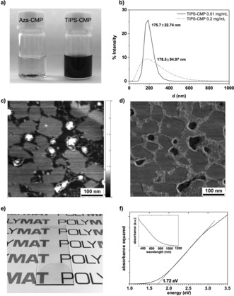
a) Dispersions of Aza‐CMP and TIPS‐CMP in TFA; b) DLS of dispersions of TIPS‐CMP in TFA; c) height (range: 2.992 nm) and d) phase AFM images of a dispersion of TIPS‐CMP in H2O/EtOH (1:1); e) drop‐cast thin film of TIPS‐CMP from a dispersion in DMF/TFA (95:5); f) Tauc plot of the TIPS‐CMP thin film (inset shows the absorption trace of the thin film).
Homogeneous, coherent, and optically transparent golden‐brownish thin films were obtained by drop casting a dispersion of TIPS‐CMP in DMF/TFA (95:5) on glass slides (Figure 3 e), which enabled the estimation of the energy gap of TIPS‐CMP by the Tauc18 method (Figure 3 f). The estimated energy gap of 1.7 eV for TIPS‐CMP falls within the values considered for semiconductors,19 and aligns well with the DFT value (2.1 eV) estimated for an individual pore (see the Supporting Information).
Since TIPS‐CMP can form homogeneous and stable dispersions that allow liquid processing, and as a proof of concept, we tested their potential application as electrocatalysts for the ORR, in which N‐doped carbon nanomaterials have shown outstanding performance.4 For this purpose, we drop cast 50 μL of a freshly prepared dispersion of TIPS‐CMP (0.2 mg mL−1) in TFA directly on a glassy‐carbon rotating‐disk electrode (catalyst loading: 140 μg cm−2) and investigated the ORR in ultrapure 0.1 m aqueous KOH. The cyclic voltammogram of an argon‐saturated KOH solution shows a featureless curve. Conversely, the cyclic voltammograms of TIPS‐CMP in O2‐saturated KOH clearly showed the onset of cathodic current as a result of the ORR at 0.75 V (vs. RHE), which is 150 mV more positive (i.e. less energy‐consuming) than the bare glassy‐carbon electrode20, 21 (Figure 4 a; see Figure S13) and highlights the catalytic performance of TIPS‐CMP. The voltammetric response is highly stable, as can be seen in the reverse scans, which almost match the forward scans at low scan rates (10 mV s−1, as also confirmed by a time‐dependent study (see Figure S14)).
Figure 4.
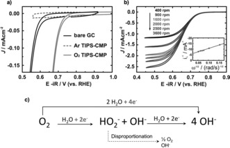
a) Cyclic voltammograms of a bare GC electrode (O2‐saturated) and after TIPS‐CMP drop‐casting (Ar‐saturated and O2‐saturated) in aqueous ultrapure 0.1 m KOH (scan rate: 10 mV s1, rotating speed: 1600 rpm). b) Cyclic voltammograms of a drop‐casted TIPS‐CMP on GC electrode at different rotating speeds in O2‐saturated aqueous 0.1 m KOH (inset: Koutecky—Levich analysis of the limiting currents measured at 0.55 V). c) Possible ORR mechanisms in alkaline solution, with the two‐ and four‐electron reaction pathways highlighted. RHE=reversible hydrogen electrode.
The ORR performance of TIPS‐CMP (with E 1/2=0.65 V vs. NHE) is in line with that observed in current state‐of‐the‐art organic frameworks and even superior in many cases (e.g. g‐C3N4, C‐COP‐P, and C‐COP‐T).22 Remarkably, whereas other organic frameworks22 require an additional carbonization step or need to be mixed with different carbonaceous supports to reach their level of ORR performance, TIPS‐CMP does not require any post‐processing to attain its electrocatalytic activity. To understand the mechanism involved in the ORR with TIPS‐CMP, we studied the process further with a rotating‐disk electrode at different rotation speeds (Figure 4 b). By representing the limiting current as a function of the rotation speed, the number of electrons exchanged in the ORR process can be estimated by the slope of the fitting line (known as Koutecky–Levich analysis). As shown in Figure 4 c, two ORR mechanisms might occur, the two‐electron (from O2 to H2O2) and four‐electron (from O2 to H2O) reaction pathways. The Koutecky–Levich plot for TIPS‐CMP shows a three‐electron process for ORR, thus pointing to the formation of both hydrogen peroxide and water as reaction products.4
We have demonstrated that the flat structure of 2D aromatic frameworks can be twisted by overcrowding the nodes of the framework with bulky and rigid TIPS substituents. Twist angles as large as 95° were estimated for TIPS‐CMP; they exceed substantially those previously observed for the parent twisted‐HATNA.13 TIPS‐CMP was found to form homogeneous dispersions upon sonication in a range of solvents, in which it underwent spontaneous exfoliation into individual layers with an average diameter of approximately 200 nm, as observed by AFM and DLS. The enhanced dispersibility observed for TIPS‐CMP has been attributed to the highly distorted aromatic framework, which results in diminished interlayer interactions that favor the exfoliation and dispersion of individual layers in organic media. Homogeneous, coherent, and optically transparent thin films were readily obtained by drop casting such dispersions. UV/Vis absorption spectroscopy of such films illustrated the semiconducting nature of TIPS‐CMP (energy gap: 1.7 eV). TIPS‐CMP modified electrodes prepared by drop casting showed enhanced ORR electrocatalytic activity (+150 mV) in comparison to the bare GC electrode without the need for any additional post‐processing step. Overall, this study shows that twisting is a very powerful strategy to enhance the dispersibility and processability of conjugated materials consisting of fused aromatic rings, even for systems that span hundreds of nanometers in two dimensions, thus opening the door to the formulation of CMPs into inks to enable large‐area and low‐cost liquid‐deposition methods.
Conflict of interest
The authors declare no conflict of interest.
Supporting information
As a service to our authors and readers, this journal provides supporting information supplied by the authors. Such materials are peer reviewed and may be re‐organized for online delivery, but are not copy‐edited or typeset. Technical support issues arising from supporting information (other than missing files) should be addressed to the authors.
Supplementary
Acknowledgements
We are grateful to the Basque Science Foundation for Science (Ikerbasque), POLYMAT, the University of the Basque Country (SGIker), the Deutsche Forschungsgemeinschaft (AU 373/3‐1 and MA 5215/4‐1), Gobierno de España/FEDER (Ministerio de Economía y Competitividad, CTQ2015‐71936‐REDT, CTQ2016‐77970‐R, and ENE2015‐66975‐C3), Gobierno Vasco (BERC program, PC2015‐1‐01(06‐37), and IT1069‐16), Diputacioń Foral de Guipuzkoa (2015‐CIEN‐000054‐01), CICECO—Aveiro Institute of Materials, POCI‐01‐0145‐FEDER‐007679 (FCT ref. UID/CTM/50011/ 2013), ON2 (NORTE‐07–0162‐FEDER‐000086), the Fund of Scientific Research—Flanders (FWO), the Internal Funds KU Leuven, the Belgian Federal Science Policy Office (IAP‐7/05), and the Nanoscale and Microscale Research Centre (NMRC, University of Nottingham, UK) for access to TEM. We have received funding for the research leading to these results from the European Union Seventh Framework Programme as a European Research Area Action (ERA‐Chemistry) and a Marie Curie Action (Career Integration Grant No. 618247) and from the European Union Framework Programme for Research and Innovation Horizon 2020 as a Future and Emerging Technologies Action (FET Open) under Grant Agreement No. 664878 (2D‐INK).
A. B. Marco, D. Cortizo-Lacalle, I. Perez-Miqueo, G. Valenti, A. Boni, J. Plas, K. Strutyński, S. De Feyter, F. Paolucci, M. Montes, A. N. Khlobystov, M. Melle-Franco, A. Mateo-Alonso, Angew. Chem. Int. Ed. 2017, 56, 6946.
Contributor Information
Dr. A. Belen Marco, http://www.polymat.eu
Prof. Dr. Aurelio Mateo‐Alonso, Email: amateo@polymat.eu
References
- 1.
- 1a. Novoselov K. S., Geim A. K., Morozov S. V., Jiang D., Zhang Y., Dubonos S. V., Grigorieva I. V., Firsov A. A., Science 2004, 306, 666–669; [DOI] [PubMed] [Google Scholar]
- 1b. Vázquez E., Giacalone F., Prato M., Chem. Soc. Rev. 2014, 43, 58–69; [DOI] [PubMed] [Google Scholar]
- 1c. Quintana M., Vazquez E., Prato M., Acc. Chem. Res. 2013, 46, 138–148; [DOI] [PubMed] [Google Scholar]
- 1d. Eigler S., Hirsch A., Angew. Chem. Int. Ed. 2014, 53, 7720–7738; [DOI] [PubMed] [Google Scholar]; Angew. Chem. 2014, 126, 7852–7872; [Google Scholar]
- 1e. Hirsch A., Englert J. M., Hauke F., Acc. Chem. Res. 2013, 46, 87–96; [DOI] [PubMed] [Google Scholar]
- 1f. Malig J., Jux N., Guldi D. M., Acc. Chem. Res. 2013, 46, 53–64; [DOI] [PubMed] [Google Scholar]
- 1g. Rodríguez-Pérez L., Herranz M. A., Martín N., Chem. Commun. 2013, 49, 3721–3735. [DOI] [PubMed] [Google Scholar]
- 2.
- 2a. Xu Y., Jin S., Xu H., Nagai A., Jiang D., Chem. Soc. Rev. 2013, 42, 8012–8031; [DOI] [PubMed] [Google Scholar]
- 2b. Colson J. W., Dichtel W. R., Nat. Chem. 2013, 5, 453–465; [DOI] [PubMed] [Google Scholar]
- 2c. Adjizian J.-J., Briddon P., Humbert B., Duvail J.-L., Wagner P., Adda C., Ewels C., Nat. Commun. 2014, 5, 5842; [DOI] [PubMed] [Google Scholar]
- 2d. Zhu G., Ren H., Porous Organic Frameworks. Design, Synthesis and Their Advanced Applications, Springer, 2015; [Google Scholar]
- 2e. Slater A. G., Cooper A. I., Science 2015, 348, aaa8075; [Google Scholar]
- 2f. Sakaushi K., Antonietti M., Acc. Chem. Res. 2015, 48, 1591–1600; [DOI] [PubMed] [Google Scholar]
- 2g. Waller P. J., Gándara F., Yaghi O. M., Acc. Chem. Res. 2015, 48, 3053–3063; [DOI] [PubMed] [Google Scholar]
- 2h. Xiang Z., Cao D., Dai L., Polym. Chem. Polymer Chem. 2015, 6, 1896–1911; [Google Scholar]
- 2i. Díaz U., Corma A., Coord. Chem. Rev. 2016, 311, 85–124; [Google Scholar]
- 2j. Segura J. L., Mancheno M. J., Zamora F., Chem. Soc. Rev. 2016, 45, 5635–5671; [DOI] [PubMed] [Google Scholar]
- 2k. Dong R., Pfeffermann M., Liang H., Zheng Z., Zhu X., Zhang J., Feng X., Angew. Chem. Int. Ed. 2015, 54, 12058–12063; [DOI] [PubMed] [Google Scholar]; Angew. Chem. 2015, 127, 12226–12231; [Google Scholar]
- 2l. Kambe T., Sakamoto R., Hoshiko K., Takada K., Miyachi M., Ryu J.-H., Sasaki S., Kim J., Nakazato K., Takata M., Nishihara H., J. Am. Chem. Soc. 2013, 135, 2462–2465. [DOI] [PubMed] [Google Scholar]
- 3.
- 3a. Kou Y., Xu Y., Guo Z., Jiang D., Angew. Chem. Int. Ed. 2011, 50, 8753–8757; [DOI] [PubMed] [Google Scholar]; Angew. Chem. 2011, 123, 8912–8916; [Google Scholar]
- 3b. Guo J., Xu Y., Jin S., Chen L., Kaji T., Honsho Y., Addicoat M. A., Kim J., Saeki A., Ihee H., Seki S., Irle S., Hiramoto M., Gao J., Jiang D., Nat. Commun. 2013, 4, 2736; [DOI] [PMC free article] [PubMed] [Google Scholar]
- 3c. Mahmood J., Lee E. K., Jung M., Shin D., Jeon I.-Y., Jung S.-M., Choi H.-J., Seo J.-M., Bae S.-Y., Sohn S.-D., Park N., Oh J. H., Shin H.-J., Baek J.-B., Nat. Commun. 2015, 6, 6486; [DOI] [PMC free article] [PubMed] [Google Scholar]
- 3d. Mahmood J., Lee E. K., Jung M., Shin D., Choi H.-J., Seo J.-M., Jung S.-M., Kim D., Li F., Lah M. S., Park N., Shin H.-J., Oh J. H., Baek J.-B., Proc. Natl. Acad. Sci. USA 2016, 113, 7414–7419. [DOI] [PMC free article] [PubMed] [Google Scholar]
- 4.
- 4a. Dai L., Xue Y., Qu L., Choi H.-J., Baek J.-B., Chem. Rev. 2015, 115, 4823–4892; [DOI] [PubMed] [Google Scholar]
- 4b. Sakaushi K., Fellinger T.-P., Antonietti M., ChemSusChem 2015, 8, 1156–1160. [DOI] [PubMed] [Google Scholar]
- 5. Zheng Y., Jiao Y., Zhu Y., Li L. H., Han Y., Chen Y., Du A., Jaroniec M., Qiao S. Z., Nat. Commun. 2014, 5, 3783. [DOI] [PubMed] [Google Scholar]
- 6.
- 6a.X. Zhang, L. Hou, A. Ciesielski, P. Samorì, Adv. Energy Mater 2016, DOI: 10.1002/aenm.201600671;
- 6b. Peng X., Peng L., Wu C., Xie Y., Chem. Soc. Rev. 2014, 43, 3303–3323. [DOI] [PubMed] [Google Scholar]
- 7.L. Peng, Y. Zhu, D. Chen, R. S. Ruoff, G. Yu, Adv. Energy Mater 2016, DOI: 10.1002/aenm.201600025.
- 8. Bonaccorso F., Bartolotta A., Coleman J. N., Backes C., Adv. Mater. 2016, 28, 6136–6166. [DOI] [PubMed] [Google Scholar]
- 9.
- 9a. Berlanga I., Ruiz-González M. L., González-Calbet J. M., Fierro J. L. G., Mas-Ballesté R., Zamora F., Small 2011, 7, 1207–1211; [DOI] [PubMed] [Google Scholar]
- 9b. Chandra S., Kandambeth S., Biswal B. P., Lukose B., Kunjir S. M., Chaudhary M., Babarao R., Heine T., Banerjee R., J. Am. Chem. Soc. 2013, 135, 17853–17861. [DOI] [PubMed] [Google Scholar]
- 10. Bunck D. N., Dichtel W. R., J. Am. Chem. Soc. 2013, 135, 14952–14955. [DOI] [PubMed] [Google Scholar]
- 11. Mitra S., Kandambeth S., Biswal B. P., Khayum M. A., Choudhury C. K., Mehta M., Kaur G., Banerjee S., Prabhune A., Verma S., Roy S., Kharul U. K., Banerjee R., J. Am. Chem. Soc. 2016, 138, 2823–2828. [DOI] [PubMed] [Google Scholar]
- 12. Khayum M. A., Kandambeth S., Mitra S., Nair S. B., Das A., Nagane S. S., Mukherjee R., Banerjee R., Angew. Chem. Int. Ed. 2016, 55, 15604–15608; [DOI] [PubMed] [Google Scholar]; Angew. Chem. 2016, 128, 15833–15837. [Google Scholar]
- 13. Choudhary S., Gozalvez C., Higelin A., Krossing I., Melle-Franco M., Mateo-Alonso A., Chem. Eur. J. 2014, 20, 1525–1528. [DOI] [PubMed] [Google Scholar]
- 14.
- 14a. Tregnago G., Fléchon C., Choudhary S., Gozalvez C., Mateo-Alonso A., Cacialli F., Appl. Phys. Lett. 2014, 105, 143304; [Google Scholar]
- 14b. Cortizo-Lacalle D., Pertegas A., Martinez-Sarti L., Melle-Franco M., Bolink H. J., Mateo-Alonso A., J. Mater. Chem. C 2015, 3, 9170–9174; [Google Scholar]
- 14c. More S., Choudhary S., Higelin A., Krossing I., Melle-Franco M., Mateo-Alonso A., Chem. Commun. 2014, 50, 1976–1979; [DOI] [PubMed] [Google Scholar]
- 14d. R. A. Pascal, Jr. , Chem. Rev. 2006, 106, 4809–4819; [DOI] [PubMed] [Google Scholar]
- 14e. Mateo-Alonso A., Chem. Soc. Rev. 2014, 43, 6311–6324; [DOI] [PubMed] [Google Scholar]
- 14f. Ball M., Zhong Y., Wu Y., Schenck C., Ng F., Steigerwald M., Xiao S., Nuckolls C., Acc. Chem. Res. 2015, 48, 267–276. [DOI] [PubMed] [Google Scholar]
- 15. An C., Guo X., Baumgarten M., Cryst. Growth Des. 2015, 15, 5240–5245. [Google Scholar]
-
16.Herein, the term “twist angle between blades” refers to the torsion angle between atoms A, B, C, and D.
- 17. Mateo-Alonso A., Kulisic N., Valenti G., Marcaccio M., Paolucci F., Prato M., Chem. Asian J. 2010, 5, 482–485. [DOI] [PubMed] [Google Scholar]
- 18. Tauc J., Mater. Res. Bull. 1968, 3, 37–46. [Google Scholar]
- 19.Given the similar pK a values of TFA (0.23) and pyrazine (0.36), and also the high volatility of TFA as compared to DMF, we can safely assume that the films were neutral after overnight vacuum drying.
- 20.The onset of cathodic current as a result of the ORR is 120 mV more negative than a standard Pt/C electrode (Pt 5 %).
- 21. Schmidt T. J., Gasteiger H. A., Stäb G. D., Urban P. M., Kolb D. M., Behm R. J., J. Electrochem. Soc. 1998, 145, 2354–2358. [Google Scholar]
- 22.
- 22a. Lyth S. M., Nabae Y., Moriya S., Kuroki S., Kakimoto M.-a., Ozaki J.-i., Miyata S., J. Phys. Chem. C 2009, 113, 20148–20151; [Google Scholar]
- 22b. Zheng Y., Jiao Y., Chen J., Liu J., Liang J., Du A., Zhang W., Zhu Z., Smith S. C., Jaroniec M., Lu G. Q., Qiao S. Z., J. Am. Chem. Soc. 2011, 133, 20116–20119; [DOI] [PubMed] [Google Scholar]
- 22c. Xiang Z., Cao D., Huang L., Shui J., Wang M., Dai L., Adv. Mater. 2014, 26, 3315–3320; [DOI] [PubMed] [Google Scholar]
- 22d. Xiang Z., Xue Y., Cao D., Huang L., Chen J.-F., Dai L., Angew. Chem. Int. Ed. 2014, 53, 2433–2437; [DOI] [PubMed] [Google Scholar]; Angew. Chem. 2014, 126, 2465–2469; [Google Scholar]
- 22e. Yang S., Feng X., Wang X., Müllen K., Angew. Chem. Int. Ed. 2011, 50, 5339–5343; [DOI] [PubMed] [Google Scholar]; Angew. Chem. 2011, 123, 5451–5455. [Google Scholar]
Associated Data
This section collects any data citations, data availability statements, or supplementary materials included in this article.
Supplementary Materials
As a service to our authors and readers, this journal provides supporting information supplied by the authors. Such materials are peer reviewed and may be re‐organized for online delivery, but are not copy‐edited or typeset. Technical support issues arising from supporting information (other than missing files) should be addressed to the authors.
Supplementary


