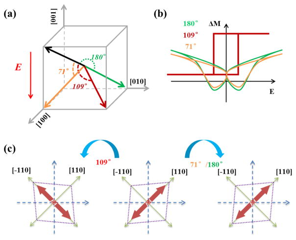
Figure 4.
Schematic of the FE-domain-switching-controlled magnetism. Schematic of (a) three FE domain switching processes of PMN-PT and (b) picture of the related M–E curves. (c) The top view looking down [001] of distortions and related in-plane magnetic easy axes (EA, red arrows) for the different FE domain switching processes, starting from a FE polarization along the [111] direction.

