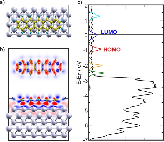
Figure 4.

(a) Top view of the most stable adsorption configuration of 5A on Ag(001) (Ag: light gray; C: gold; H: light blue). (b) Horizontal (top) and vertical two-dimensional cuts showing the charge density differences induced by 5A adsorption on the Ag(001) substrate. The arrows indicate where the horizontal cut has been made. Red shows accumulation and blue depletion of charge, respectively. (c) PDOS obtained for the 5A/Ag(001) interface using the GGA functional. The DOS projected onto the Ag atoms (black) has been reduced for better visibility. In addition, the projections on the molecular orbitals are shown for LUMO+1 (cyan), LUMO (blue), HOMO (red), HOMO–1 (orange), and HOMO–2 (dark green).
