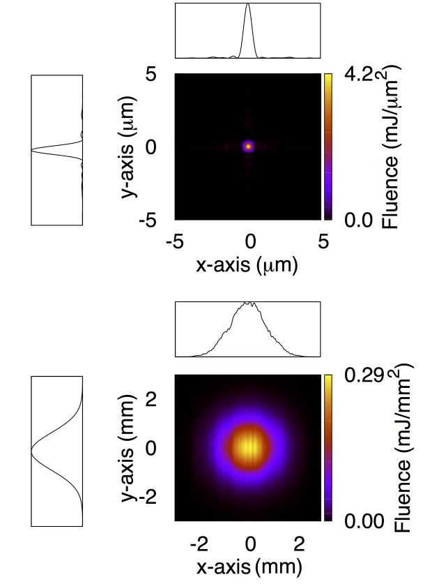
Figure 4.
Estimated intensity distribution at the 1 µm focal plane (top) and at the entrance aperture of the FEH (bottom) after completion of the X-ray mirror upgrade. Lineouts are also shown. Each lineout has been obtained by integrating the two-dimensional intensity distribution along one of the axes. Spatial axis labels for the lineouts have been omitted for simplicity, and are the same as the corresponding two-dimensional maps.

