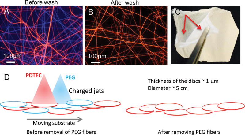
Figure 1. PDTEC:PEG electrospun fibers before and after PEG removal.

Optical microscopy images of fluorescent-labeled electrospun fibers before (A) and after (B) washing with water to remove PEG fibers. PEG fibers are blue and PDTEC fibers are red. Scale bar = 200 μm. (C) Layered structure in co-spun mat after PEG removal. The arrows point to the two delaminated layers. (D) Schematic of the deposition of PDTEC and PEG to illustrate the formation of a layered structure. For clarity, patches of PEG or PDTEC fibers are shown as discs, and the fibers inside the patches as well those between them are not shown. In the left diagram, PEG and PDTEC jets with same type of charge repel each other, and are shown depositing separate patches to illustrate weak intermingling of the two polymer fibers. The right diagram shows that upon the dissolution of the PEG segments by washing, weakly interwoven PDTEC discs are left behind.
