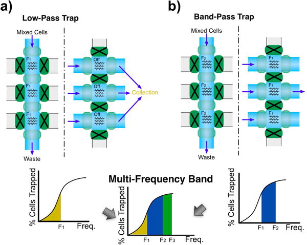
Fig. 4.

a) Low-pass trap configuration. The trapping frequency is set at F1 in all trapping sites and collection is done with DEP field off. b) Band-pass trap configuration. Trapping at F2 and collecting cells while DEP frequency F1 is on yields cells that would trap between these frequencies. A multi-frequency band pass configuration of increasing frequencies F1, F2 and F3 can be conceived as a combination of a) and b)
