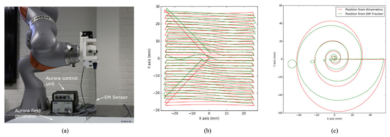
Fig. 5.
(a) Image of the assembly instrument with EM sensor integrated at the tip; Scanning trajectories from the kinematic data and EM tracker projected to the XY plane as the z position of the shaft remains constant throughout the scan; (b) Raster scan with an area (50 × 50) mm2 with 1.5 mm steps along the y axis; (c) Spiral scan with a maximum radius of 50 mm and 5 revolutions.

