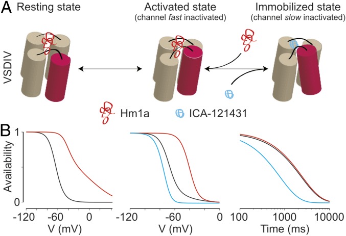
Fig. 6.
Model for VSDIV-controlled inactivation gating in Nav1.1. (A) Sequential states of VSDIV are shown with the functional state of the ion channel coupled to each position shown above. In this model, Hm1a stabilizes the resting state of the voltage sensor, whereas ICA exclusively promotes movement from the activated to the immobilized state. (B) A three-state model of sequential VSDIV movements with simple rate changes recapitulating the effects of Hm1a and ICA on Nav1.1 (Table S1). Simulated SSI (Left), voltage dependence of slow inactivation (Middle), and time dependence of entry into slow inactivation (Right) are shown. WT, Hm1a, and ICA models are shown in black, red, and blue, respectively.

