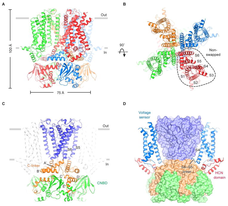
Figure 1. Architecture of the human HCN1 channel.
(A and B) Structure of the channel tetramer in the ligand-free state, viewed parallel to the membrane (A) or from the extracellular side (B). Each subunit is shown in a different color. Gray bars represent approximate boundaries of the membrane bilayer.
(C and D) Domain organization of the HCN channel. In (C), the pore domain (helices S5 and S6) is colored blue, the C-linker disk (A′- and B′-helices) and four following helices (C′- to F′-helices) are colored orange, and the CNBD is colored green. In (D), the voltage sensors and the HCN domains are shown as ribbons, whereas the pore and C-terminal domains are in surface representation. The voltage sensor from the subunit nearest to the viewer is removed for clarity.
See also Figures S1, S2, S3 and S5.

