
Figure 2.
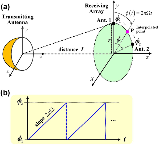
Interpolation of the antenna array signals. (a) Schematic of the interpolation algorithm. The OAM wave is detected using two antennas deployed transversely across the doughnut-shaped beam. These two antenna signals are multiplied by weighting coefficients and added together. This interpolated signal has the characteristics of a signal that would be received by an antenna positioned at a point between the two antennas. By varying the weighting coefficients with time, the location of the interpolated point can be made to move from one antenna to the other. (b) The rotation angle of the interpolated point P which rotates between Ant. 1 and Ant. 2 with speed Ω.