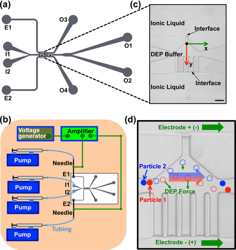
Figure 1.

The DEP device with ionic liquid electrodes. (a) A sketch of the microfluidic channel system in the device. (b) A schematic of the experimental setup. (c) A zoom-in view of the ionic liquid electrodes and the main channel on the real image showing the stable interface formed between the ionic liquid and the DEP buffer. Scale bar: 100 μm. (d) A schematic showing the mechanism of the particle and cell separation. Particles 1 and 2 with different electrical properties and size are deflected by the DEP force differently and can be separated from each other in the electrode region. The dashed circles represent the intermediate position of the particles.
