Fig. 3.
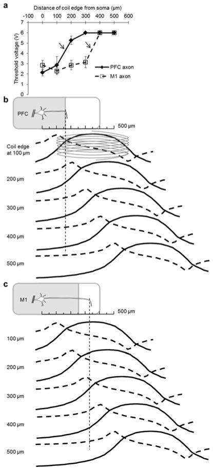
Cell type-dependent sensitivity of L5 PNs to stimulation along the axon. (a) Mean threshold of the coil-input voltage needed to elicit spiking in L5 PNs as a function of the distance between the coil edge and the soma (PFC: filled diamond points and solid line (n=9); M1: open square points and dashed line (n=5)). Bars represent S.E. The maximum input voltage to the coil was limited to 6 V so data points at that level underestimate actual thresholds. Arrows indicate a sudden transition in threshold voltage (see text). (b) (top) Schematic illustration of a PFC PN. The axon extends along the plane of the coronal slice but bends into the slice at a distance of ~150 μm from the soma; the thin dashed line indicates the bend location. (lower traces) Each row represents the induced E-field (solid trace) and its spatial gradient (dashed trace) arising from a coil positioned at a different location along the proximal axon (distances are given at left). (c) Analogous to (b) but for M1 PNs. Note the axon bend in M1 PNs occurs further from the soma.

