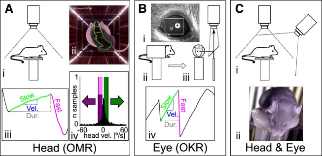
Fig. 1.
Recording configurations for OMR and OKR measurements. Three different apparatus configurations were used to evaluate OMR (A), OKR (B), and eye movements in freely behaving animals (C). Experiments in A and B were carried out using the same conditions as presented in Kretschmer et al. (2015). A: measurement of head movements (OMR). i, Schematic of recording configuration. The animal moves unrestrained on a platform and is monitored from above with a camera fitted with an infrared (IR) high-pass filter. ii, Example of a frame recorded by the top camera, with annotations of the automated online tracking algorithm. Four screens are presenting a stimulus consisting of vertical sinusoidal bars, and the arena is illuminated with IR LED strips placed at the corners between the screens. The green dot represents the center of mass for the automatically detected mouse contour (green outline), and the two red dots define the head orientation of the animal (for examples, see Supplementary Movies S1 and S2). iii, Example and naming convention for the manual trace annotation. Tracking movements were identified from the automatically derived head tracking trace. x-Axis is time, y-axis is head angle. The onset and offset of the slow (“tracking”; green) and fast (“reset”; magenta) phases were derived, and then the duration (Dur.; gray dashed line) and the velocity (Vel.; blue dashed line) of the slow phase were computed. iv, Calculation of the OMR index. For the automated analysis of head movements, the pairwise head angle differentials between all successive frames of the recording were determined (histogram, normalized to total number of observations). We then defined windows of (+2 to −10°/s) around the stimulus speed (±12°/s, black vertical lines) for the correct (green) and incorrect (magenta) directions and counted the total correct (Tc) and incorrect (Ti) movements contained within the two windows. The OMR index was computed as Tc/Ti. B: measurements of eye movements (OKR). i, example of pupil tracking using the ISCAN video camera. Pupil position is calculated relative to an IR corneal reflection landmark, and the pixel displacement is converted to angular coordinates using the calibration technique adapted from Stahl et al. (2000). ii and iii, Schematics of the recording setup, showing side view (ii) and front view (iii) of the mouse in the holder. The animal is restrained using an implanted head mount, and the eye image is projected to the camera through a 45° IR reflective mirror (placed in a plane parallel to the axis of the mouse). iv, Eye movements were analyzed semiautomatically. Several parameters were derived from the ISCAN recorded traces: the onset and offset, the duration (gray dashed line), the velocity (blue dashed line) of the slow (tracking) phase (green), and the onset of the fast (reset) phase (magenta). The automatically detected phases were checked manually in a second step. C: for simultaneous head and eye detection, we recorded the head movements of the unrestrained mouse as in A while imaging the eyes with an additional camera fixed onto the arena wall at 12-cm elevation above the mouse platform (i). ii, Pupil locations (green circles) and the nasal edges of the eyes (magenta cross) are determined by a pattern-matching algorithm, whereas head position was collected using the same protocol as in A.

